

 英语
英语 葡萄牙语
葡萄牙语 西班牙语
西班牙语 русский
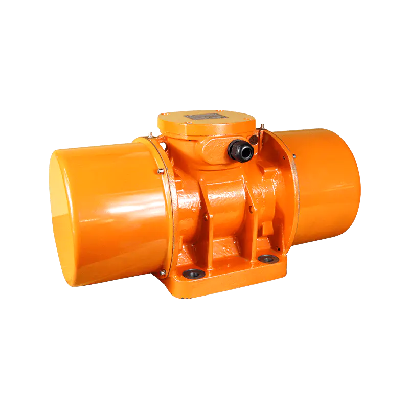
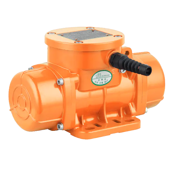
Equipment designers specifying vibratory feeder systems keep running into the same tuning question: what actually determines the right amplitude and frequency combination for a feeder vibrator driving a specific trough design, and does a mismatch here explain the uneven material flow problems that plague otherwise well-built feeder systems? Manufacturers supplying bulk material handling, aggregate processing, and concrete production equipment increasingly find eccentric weight setting, mounting rigidity, and trough natural frequency shape flow consistency more directly than motor horsepower alone.
Amplitude Adjustment and Material Flow Rate
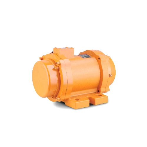
Amplitude, controlled through eccentric weight positioning on this style of motor, determines how far the trough surface travels during each vibration cycle, and this travel distance directly affects how quickly bulk material moves along a feeder's surface. Wider amplitude settings move material faster but can cause fine particles to become airborne or bounce unpredictably, while narrower amplitude settings move material more gently at the cost of reduced throughput, a trade-off equipment designers increasingly tune against the specific particle size distribution and density of the material a vibratory feeder handles.
Frequency selection works alongside amplitude rather than independently, since the combination of these two parameters determines the acceleration a trough surface experiences during each cycle. A feeder vibrator operating at higher frequency with lower amplitude can achieve comparable material movement to a lower-frequency, higher-amplitude setup, though the resulting particle motion pattern differs enough that fine, sticky, or irregularly shaped materials often respond better to one combination over the other.
|
Tuning Factor |
Effect on Flow |
Common Adjustment Range |
|
Amplitude |
Material travel distance per cycle |
1mm to 8mm depending on application |
|
Frequency |
Cycle rate, particle acceleration |
1000 to 3600 RPM typical range |
|
Eccentric weight angle |
Force output magnitude |
Adjustable in incremental steps |
|
Mounting rigidity |
Energy transfer efficiency |
Rigid frame mounting preferred |
Mounting Rigidity and Energy Transfer
A vibrator mounted to a flexible or poorly reinforced trough loses a meaningful portion of its vibrational energy to structural flex rather than transferring that energy into productive material movement. Manufacturers increasingly specify reinforced mounting plates and cross-bracing at the industrial vibration motor attachment point specifically to minimize this energy loss, since a trough that flexes under vibration wastes motor output and can develop fatigue cracking at the mounting welds over an extended service life.
Bolt torque specifications at the mounting interface deserve particular attention, since an under-torqued mounting bolt allows micro-movement between the motor housing and trough structure that gradually loosens the connection further, eventually leading to a mounting failure that a properly torqued and periodically inspected connection would avoid entirely.
Natural Frequency and Resonance Avoidance
Every trough structure has a natural resonant frequency determined by its mass, material, and geometry, and operating a feeder vibrator at or near this resonant frequency can amplify vibration dramatically beyond what the motor alone would produce, risking structural damage rather than improved material flow. Equipment designers increasingly calculate the natural frequency during the design phase and select a vibrator operating frequency positioned safely away from this resonant point, since operating near resonance produces unpredictable and potentially dangerous vibration amplitudes that standard motor specifications don't account for.
Twin-motor synchronized systems, common on larger feeder installations, introduce an additional tuning consideration since two motors need synchronized rotation to produce the linear vibration pattern these systems depend on, rather than the circular motion a single unsynchronized motor would generate on its own. Phase alignment between the two motors needs periodic verification during commissioning and routine maintenance, since drift in synchronization gradually shifts the vibration pattern away from the linear motion the system was designed to produce, degrading feed consistency well before an obvious mechanical fault would otherwise signal a problem.
Sourcing Considerations for Feeder Applications
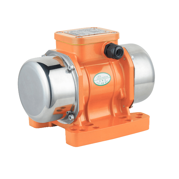
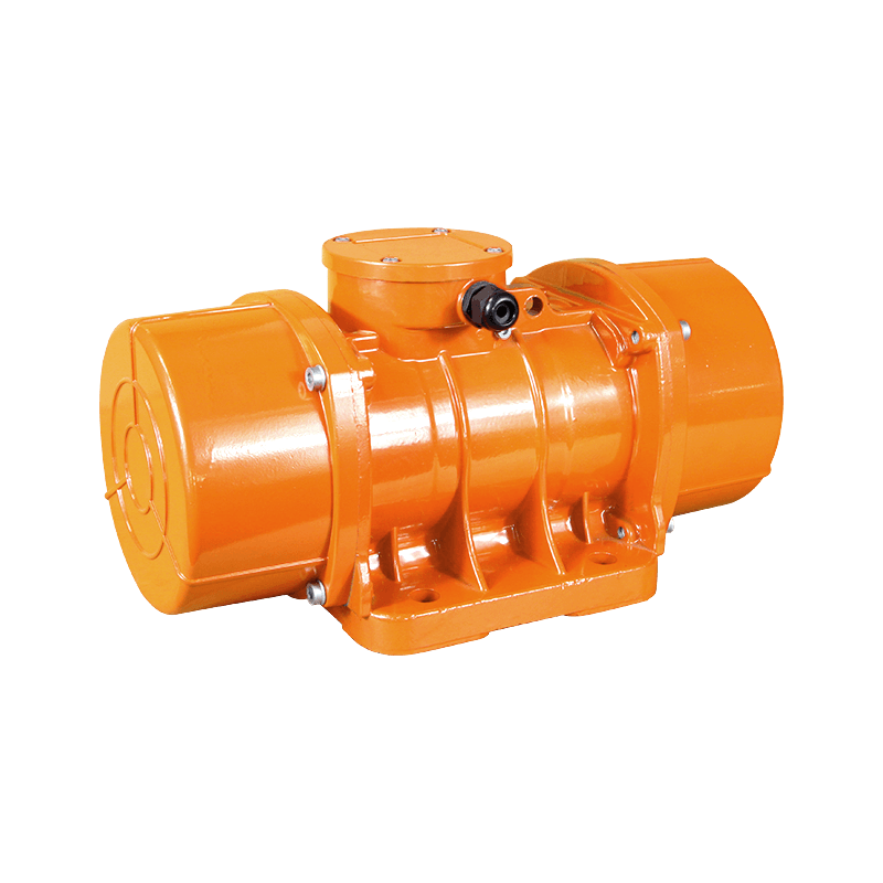
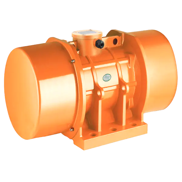
Buyers specifying a feeder vibrator for a new equipment design increasingly request force output curves across the full adjustable amplitude range rather than a single rated force figure, since actual operating conditions rarely match a datasheet's single reference point exactly. Guangling documents amplitude adjustment range, mounting specifications, and twin-motor synchronization compatibility for its feeder vibrator lineup, giving equipment designers a technical reference matched to specific trough geometry and material handling requirements.


 Tel: + 86-576-86320988
 Fax: + 86-576-86333217
 E-mail:
  Add: Dayangcheng Industrial Zone, daxi, wenling, zhejiang, china
